Thursday 13 May 2010

Home Router Setup - Part 2: Interfaces & Services

In this post I'll be setting up my network interfaces and some network services, DNS and DHCP.

Below is a diagram of the lab I'll be using.


Part 2 - Interfaces and Services


Here I will set up the 2 network interfaces and remove CDP from the Test Network interface.

Router1(config)#interface ethernet 0
Router1(config-if)#ip address 10.0.2.254 255.255.255.0
Router1(config-if)#no cdp enable
Router1(config-if)#exit

Router1(config)#interface ethernet 1
Router1(config-if)#ip address 10.0.1.254 255.255.255.0
Router1(config-if)#no shut
Router1(config-if)#exit


I configure the router to use the Extreme router as it's default gateway. I will also configure it to use OpenDNS name servers and to resolve DNS queries for other network hosts.

Router1(config)#ip route 0.0.0.0 0.0.0.0 10.0.1.1
Router1(config)#ip domain-lookup
Router1(config)#ip name-server 208.67.222.222
Router1(config)#ip name-server 208.67.220.220
Router1(config)#ip dns server
Router1(config)#exit


Next I configure DHCP for the Test Network.

Router1(config)#service dhcp
Router1(config)#ip dhcp pool TEST_NETWORK_DHCP_POOL
Router1(dhcp-config)#network 10.0.2.0 /24
Router1(dhcp-config)#domain-name walliford.local
Router1(dhcp-config)#dns-server 10.0.2.254
Router1(dhcp-config)#default-router 10.0.2.254
Router1(dhcp-config)#lease 7
Router1(dhcp-config)#exit


I include exclusions so only 10.0.2.10 - 10.0.2.20 are used for DHCP clients.

Router1(config)#ip dhcp excluded-address 10.0.2.1 10.0.2.9
Router1(config)#ip dhcp excluded-address 10.0.2.21 10.0.2.255
Router1(config)#end

Wednesday 12 May 2010

Home Router Setup - Part 1: Ports

The next few posts will be a series about the setup of a Cisco 800 Series router as a home router. I will detail everything from setting up the interfaces, users, DNS, DHCP, SSH, NAT and more.

Below is a diagram that illustrates the network layout for this series of posts.


  • Lab Network - 10.0.1.0/24
  • Test Network - 10.0.2.0/24


Part 1 - Initial Configuration

In this part I will configure my ports and apply some security to the router.


I name the router, apply an enable password and create a banner.

Router#configure terminal
Router(config)#hostname Router1
Router1(config)#enable secret cisco123
Router1(config)#banner motd % No Unauthorised Access %


I create a local user.

Router1(config)#username bob secret cisco123
Router1(config)#aaa new-model
Router1(config)#aaa authentication login local_auth local


I set the domain, create SSH keys and apply some SSH settings.

Router1(config)#ip domain-name walliford.local
Router1(config)#crypto key generate rsa general-keys modulus 1024

The name for the keys will be: Router1.walliford.local
% The key modulus size is 1024 bits
% Generating 1024 bit RSA keys, keys will be non-exportable...[OK]

Router1(config)#ip ssh time-out 120
Router1(config)#ip ssh version 2
Router1(config)#ip ssh authentication-retries 2


I create an ACL which I will be applying to my telnet ports

Router1(config)#ip access-list standard ADMIN_ACCESS
Router1(config-std-nacl)#permit 10.0.1.0 0.0.0.255 log
Router1(config-std-nacl)#deny any log
Router1(config-std-nacl)#exit


I configure the console port to use the local user account and apply some timeout values.

Router1(config)#line console 0
Router1(config-line)#logging synchronous
Router1(config-line)#login authentication local_auth
Router1(config-line)#exec-timeout 30 0
Router1(config-line)#exit


I apply several settings to the Aux port so it cannot be used.

Router1(config)#line aux 0
Router1(config-line)#no password
Router1(config-line)#no exec
Router1(config-line)#exec-timeout 0 0
Router1(config-line)#transport input none
Router1(config-line)#exit


I configure my telnet ports to use SSH and telnet only and the local user account. I apply some timeout values and apply the ACL so only hosts from the Lab network can access the router.

Router1(config)#line vty 0 4
Router1(config-line)#logging synchronous
Router1(config-line)#login authentication local_auth
Router1(config-line)#transport input ssh telnet
Router1(config-line)#exec-timeout 30 0
Router1(config-line)#access-class ADMIN_ACCESS in
Router1(config-line)#end


I prevent 3 of the 5 telnet ports from being used.

Router1(config)#line vty 2 4
Router1(config-line)#transport input none
Router1(config-line)#exit


I set the clock, timezone and daylight saving settings.

Router1(config)#clock timezone GMT 0
Router1(config)#clock summer-time BST recurring last Sun Mar 2:00 last Sun Oct 2:00
Router1(config)#end
Router1#clock set 21:24:00 12 May 2010


I apply timeout values to login attempts to prevent brute-force attacks.

Router1(config)#login block-for 20 attempts 3 within 20
Router1(config)#login delay 2

Sunday 9 May 2010

Frame Relay - Point to Point

In this post I will configure my lab to use frame relay in a point to point configuration. Below is a diagram of the lab I will be using.


R0

R0#configure terminal
Enter configuration commands, one per line. End with CNTL/Z.
R0(config)#interface serial 0/0
R0(config-if)#encapsulation frame-relay
R0(config-if)#exit

R0(config)#interface serial 0/0.100 point-to-point
R0(config-subif)#ip address 192.168.1.1 255.255.255.0
R0(config-subif)#frame-relay interface-dlci 100
R0(config-fr-dlci)#exit
R0(config-subif)#exit

R0(config)#interface serial 0/0.101 point-to-point
R0(config-subif)#ip address 192.168.2.1 255.255.255.0
R0(config-subif)#frame-relay interface-dlci 101
R0(config-fr-dlci)#exit
R0(config-subif)#exit

R0(config)#interface serial 0/0
R0(config-if)#no shut


R1

R1(config)#interface serial 0/0
R1(config-if)#encapsulation frame-relay
R1(config-if)#exit

R1(config)#interface serial 0/0.200 point-to-point
R1(config-subif)#ip address 192.168.1.2 255.255.255.0
R1(config-subif)#frame-relay interface-dlci 200
R1(config-fr-dlci)#exit
R1(config-subif)#exit

R1(config)#interface serial 0/0
R1(config-if)#no shutdown


R2

R2(config)#interface serial 0/0
R2(config-if)#encapsulation frame-relay
R2(config-if)#exit

R2(config)# interface serial 0/0.300 point-to-point
R2(config-subif)#ip address 192.168.2.2 255.255.255.0
R2(config-subif)#frame-relay interface-dlci 300
R2(config-fr-dlci)#exit
R2(config-subif)#exit

R2(config)#interface serial 0/0
R2(config-if)#no shutdown


Show Commands


R2#show frame-relay pvc
PVC Statistics for interface Serial0/0 (Frame Relay DTE)

Active Inactive Deleted Static
Local 1 0 0 0
Switched 0 0 0 0
Unused 0 0 0 0

DLCI = 300, DLCI USAGE = LOCAL, PVC STATUS = ACTIVE, INTERFACE = Serial0/0.300

input pkts 349 output pkts 358 in bytes 31010
out bytes 30951 dropped pkts 0 in pkts dropped 0
out pkts dropped 0 out bytes dropped 0
in FECN pkts 0 in BECN pkts 0 out FECN pkts 0
out BECN pkts 0 in DE pkts 0 out DE pkts 0
out bcast pkts 344 out bcast bytes 29735
5 minute input rate 0 bits/sec, 0 packets/sec
5 minute output rate 0 bits/sec, 0 packets/sec
pvc create time 00:32:46, last time pvc status changed 00:31:55


R2#show frame-relay lmi
LMI Statistics for interface Serial0/0 (Frame Relay DTE) LMI TYPE = ANSI
Invalid Unnumbered info 0 Invalid Prot Disc 0
Invalid dummy Call Ref 0 Invalid Msg Type 0
Invalid Status Message 0 Invalid Lock Shift 0
Invalid Information ID 0 Invalid Report IE Len 0
Invalid Report Request 0 Invalid Keep IE Len 0
Num Status Enq. Sent 25 Num Status msgs Rcvd 26
Num Update Status Rcvd 0 Num Status Timeouts 0
Last Full Status Req 00:00:56 Last Full Status Rcvd 00:00:56


R2# sh frame-relay map
Serial0/0.300 (up): point-to-point dlci, dlci 300(0x12C,0x48C0), broadcast
status defined, active


After configuring frame relay I am able to ping routers on the same network but not the other networks, so currently R2 cannot talk to R1.


R2#ping 192.168.1.1
Type escape sequence to abort.
Sending 5, 100-byte ICMP Echos to 192.168.1.1, timeout is 2 seconds:
.....
Success rate is 0 percent (0/5)


I have no route to the 192.168.1.0 network in my routing table.


R2#sh ip route
Codes: C - connected, S - static, R - RIP, M - mobile, B - BGP
D - EIGRP, EX - EIGRP external, O - OSPF, IA - OSPF inter area
N1 - OSPF NSSA external type 1, N2 - OSPF NSSA external type 2
E1 - OSPF external type 1, E2 - OSPF external type 2
i - IS-IS, su - IS-IS summary, L1 - IS-IS level-1, L2 - IS-IS level-2
ia - IS-IS inter area, * - candidate default, U - per-user static route
o - ODR, P - periodic downloaded static route
Gateway of last resort is not set
C 192.168.2.0/24 is directly connected, Serial0/0.300


To fix this problem I enable EIGRP on all my routers using the config below.


R2#conf t
Enter configuration commands, one per line. End with CNTL/Z.
R2(config)#router eigrp 10
R2(config-router)#network 192.168.0.0 0.0.255.255
R2(config-router)#end


Now I try again.


R2#ping 192.168.1.1
Type escape sequence to abort.
Sending 5, 100-byte ICMP Echos to 192.168.1.1, timeout is 2 seconds:
!!!!!
Success rate is 100 percent (5/5), round-trip min/avg/max = 4/7/12 ms


And my routing table shows the routes created by EIGRP.


R2#show ip route
Codes: C - connected, S - static, R - RIP, M - mobile, B - BGP
D - EIGRP, EX - EIGRP external, O - OSPF, IA - OSPF inter area
N1 - OSPF NSSA external type 1, N2 - OSPF NSSA external type 2
E1 - OSPF external type 1, E2 - OSPF external type 2
i - IS-IS, su - IS-IS summary, L1 - IS-IS level-1, L2 - IS-IS level-2
ia - IS-IS inter area, * - candidate default, U - per-user static route
o - ODR, P - periodic downloaded static route
Gateway of last resort is not set
D 192.168.1.0/24 [90/2681856] via 192.168.2.1, 00:01:20, Serial0/0.300
C 192.168.2.0/24 is directly connected, Serial0/0.300

Friday 7 May 2010

Frame-Relay - Multipoint

In this post I'll detail the configuration used to set up frame-relay in a multipoint configuration for the lab shown in the diagram below.


R0

R0(config)#interface serial 0/0
R0(config-if)#ip address 192.168.1.1 255.255.255.0
R0(config-if)#encapsulation frame-relay
R0(config-if)#no shut

R0(config-if)#frame-relay map ip 192.168.1.2 100 broadcast
R0(config-if)#frame-relay map ip 192.168.1.3 101 broadcast
R0(config-if)#end


R1

R1(config)#interface serial 0/0
R1(config-if)#ip address 192.168.1.2 255.255.255.0
R1(config-if)#encapsulation frame-relay
R1(config-if)#no shut

R1(config-if)#frame-relay map ip 192.168.1.1 200 broadcast
R1(config-if)#frame-relay map ip 192.168.1.3 200 broadcast
R1(config-if)#end


R2

R2(config)#interface serial 0/0
R2(config-if)#ip address 192.168.1.3 255.255.255.0
R2(config-if)#encapsulation frame-relay
R2(config-if)#no shut
R2(config-if)#exit

R2(config)#interface serial 0/0
R2(config-if)#frame-relay map ip 192.168.1.1 300 broadcast
R2(config-if)#frame-relay map ip 192.168.1.2 300 broadcast
R2(config-if)#end


Show Commands

R2#show frame-relay lmi

LMI Statistics for interface Serial0/0 (Frame Relay DTE) LMI TYPE = ANSI
Invalid Unnumbered info 0 Invalid Prot Disc 0
Invalid dummy Call Ref 0 Invalid Msg Type 0
Invalid Status Message 0 Invalid Lock Shift 0
Invalid Information ID 0 Invalid Report IE Len 0
Invalid Report Request 0 Invalid Keep IE Len 0
Num Status Enq. Sent 168 Num Status msgs Rcvd 80
Num Update Status Rcvd 0 Num Status Timeouts 89
Last Full Status Req 00:00:04 Last Full Status Rcvd 00:00:04


R2#show frame-relay map
Serial0/0 (up): ip 192.168.1.1 dlci 300(0x12C,0x48C0), static,
broadcast,
CISCO, status defined, active
Serial0/0 (up): ip 192.168.1.2 dlci 300(0x12C,0x48C0), static,
broadcast,
CISCO, status defined, active


Debug Commands

R2#debug frame-relay lmi interface serial 0/0
Frame Relay LMI debugging is on
Displaying lmi data from interface Serial0/0 only
*Mar 1 00:58:02.583: Serial0/0(out): StEnq, myseq 100, yourseen 97, DTE up
*Mar 1 00:58:02.587: datagramstart = 0x7A019D4, datagramsize = 14
*Mar 1 00:58:02.587: FR encap = 0x00010308
*Mar 1 00:58:02.587: 00 75 95 01 01 01 03 02 64 61
*Mar 1 00:58:02.595:
*Mar 1 00:58:02.607: Serial0/0(in): Status, myseq 100, pak size 14
*Mar 1 00:58:02.607: RT IE 1, length 1, type 1
*Mar 1 00:58:02.607: KA IE 3, length 2, yourseq 98, myseq 100

Sunday 18 April 2010

Time Based Access Control Lists

This is just a quick post to show how to configure Time Based Access Control Lists. My aim is to only allow telnet access to the Jet Direct in the Test network between 18:00 and 23:59 on a daily basis.

So this post makes sense I should mention that I am using the network in the diagram below and I am NAT'ing 10.0.1.243 to the host in the Test network on 10.0.2.10.


Router1

Create a static NAT mapping to the Jet Direct Printer

Router1(config)#ip nat inside source static 10.0.2.10 10.0.1.243


I then check I can ping the Jet Direct and telnet to it.

MacBook

MacBook:~ syn$ ping -c 2 10.0.1.243
PING 10.0.1.243 (10.0.1.243): 56 data bytes
64 bytes from 10.0.1.243: icmp_seq=0 ttl=59 time=9.490 ms
64 bytes from 10.0.1.243: icmp_seq=1 ttl=59 time=3.068 ms


MacBook:~ syn$ telnet 10.0.1.243
Trying 10.0.1.243...
Connected to 10.0.1.243.
Escape character is '^]'.

HP JetDirect

Please type "?" for HELP, or "/" for current settings
> exit
EXITING WITHOUT SAVING ANY ENTRIES
> Connection closed by foreign host.


Router1

Now I create the access list.

Router1(config)#ip access-list extended TELNET_TO_JETDIRECT
Router1(config-ext-nacl)#permit tcp 10.0.1.0 0.0.0.255 10.0.1.243 0.0.0.0 eq 23 time-range EVENING log
Router1(config-ext-nacl)#deny tcp 10.0.1.0 0.0.0.255 10.0.1.243 0.0.0.0 eq 23 log
Router1(config-ext-nacl)#permit ip any any
Router1(config-ext-nacl)#exit
Bold

I create a time range for the ACL

Router1(config)#time-range EVENING
Router1(config-time-range)#periodic daily 18:00 to 23:59


I check the ACL

Router1#sh ip access-lists
Extended IP access list TELNET_TO_JETDIRECT
10 permit tcp 10.0.1.0 0.0.0.255 host 10.0.2.10 eq telnet log time-range EVENING (active)
20 deny tcp 10.0.1.0 0.0.0.255 host 10.0.2.10 eq telnet log
30 permit ip any any


I apply the ACL to an interface

Router1(config)#interface ethernet 1
Router1(config-if)#ip access-group TELNET_TO_JETDIRECT in
Router1(config-if)#end


I check the ACL has applied

Router1#sh ip interface ethernet 1 | include Inbound
Inbound access list is TELNET_TO_JETDIRECT


Recheck the ACL after telneting to the JetDirect

Router1#sh ip access-lists
Extended IP access list TELNET_TO_JETDIRECT
5 permit tcp 10.0.1.0 0.0.0.255 host 10.0.1.243 eq telnet log time-range EVENING (active) (9 matches)
20 deny tcp 10.0.1.0 0.0.0.255 host 10.0.1.243 eq telnet log
30 permit ip any any (60 matches)


Sunday 21 March 2010

Configure NTP

In this post I will go through the steps to configure my router to use a NTP server as a time source.

First I will check the current configuration. I will then ping the public NTP server before setting up the router to use it.


router1#sh clock detail
23:18:28.123 GMT Sun Mar 21 2010
Time source is user configuration

router1#ping 130.88.203.12
Type escape sequence to abort.
Sending 5, 100-byte ICMP Echos to 130.88.203.12, timeout is 2 seconds:
!!!!!
Success rate is 100 percent (5/5), round-trip min/avg/max = 24/24/24 ms

router1#conf t
Enter configuration commands, one per line. End with CNTL/Z.
router1(config)#ntp server 130.88.203.12


Useful show commands to check the NTP settings are:

show ntp status
show ntp associations

Terminal Emulation Settings

This is just a very brief post to list the correct settings that are used to connect to the router or switch using a terminal program such as HyperTerminal and the console cable.

Bits per sec    :  9600 
Data bits : 8
Parity : none
Stop bits : 1
Flow control : none


Rarely some routers may require different Bits per second settings. Simply try 1200, 2400 or 4800.

Saturday 20 March 2010

Configure Time & Date

In this short post I will configure my router with the correct timezone, time and date.


router1#sh clock detail
*01:56:43.478 UTC Mon Oct 19 2009
No time source


router1#conf t
Enter configuration commands, one per line. End with CNTL/Z.
router1(config)#clock timezone GMT 0
router1(config)#end


router1#sh clock detail
*01:59:54.390 GMT Mon Oct 19 2009
No time source


router1#clock set 14:10:00 20 MARCH 2010


router1#sh clock detail
14:10:16.183 GMT Sat Mar 20 2010
Time source is user configuration

Thursday 18 March 2010

Static NAT & Dynamic NAT with Overload

In this short post I will configure my router allow to NAT a single port only.


router1#conf t
Enter configuration commands, one per line. End with CNTL/Z.
router1(config)#ip nat inside source static udp 10.0.2.2 514 10.0.1.245 514 extendable


This command will allow the router accept syslog messages sent to UDP port 514 on 10.0.1.245 and translate them to UDP 514 on 10.0.2.2 which is the syslog server. Only port 514 will be available for translation.

Configure a DNS Server

In this short post I will configure my router to act as a DNS server for hosts on my network.


router1#conf t
Enter configuration commands, one per line. End with CNTL/Z.
router1(config)#ip domain name lab.local
router1(config)#ip domain-lookup
router1(config)#ip name-server 8.8.8.8
router1(config)#ip dns server


The router will now pass and DNS requests to 8.8.8.8 (Google) to resolve.

Tuesday 9 March 2010

Static NAT

In this post I will configure a Static NAT entry on Router1 for the Win7 host. I'll be using the network in the diagram below.


First I remove the NAT configuration from my last post.


router1(config)#no ip nat inside source list NAT pool NAT_POOL overload
Dynamic mapping in use, do you want to delete all entries? [no]: y


Now I configure NAT to map Win7 (10.0.2.1) to 10.0.1.240


router1(config)#ip nat inside source static 10.0.2.1 10.0.1.240


I verify I can reach the internet from the NAT'd host and check the NAT translations


router1(config)#do sh ip nat tran
Pro Inside global Inside local Outside local Outside global
tcp 10.0.1.240:1328 10.0.2.1:1328 208.43.202.17:80 208.43.202.17:80

Dynamic NAT Using Pools

In this post I will remove my previous NAT entry and create a pool of addresses to use for NAT. I'll be using the network in the diagram below and configuring Router1.


First I'll remove the previous NAT (from my last post) configuration.


router1(config)#no ip nat inside source list NAT interface Ethernet0 overload
Dynamic mapping in use, do you want to delete all entries? [no]: yes


After removing the config I verify that I cannot access the internet or ping the internet from the Win7 host.

Now I create a NAT pool with three addresses.


router1(config)#ip nat pool NAT_POOL 10.0.1.250 10.0.1.252 netmask 255.255.255.0


I already have the NAT access-list created from my previous post so I'll use that again.


router1(config)#ip nat inside source list NAT pool NAT_POOL overload


Now I access the internet from the Win7 host and verify that I am being NAT'd.


router1#sh ip nat translations
Pro Inside global Inside local Outside local Outside global
tcp 10.0.1.251:1231 10.0.2.1:1231 208.43.202.17:80 208.43.202.17:80


I can also check the NAT statistics.


router1#sh ip nat statistics
Total active translations: 41 (0 static, 41 dynamic; 41 extended)
Outside interfaces:
Ethernet0
Inside interfaces:
Ethernet1
Hits: 24714 Misses: 1339
CEF Translated packets: 25094, CEF Punted packets: 1907
Expired translations: 1666
Dynamic mappings:
-- Inside Source
[Id: 3] access-list NAT pool NAT_POOL refcount 41
pool NAT_POOL: netmask 255.255.255.0
start 10.0.1.250 end 10.0.1.252
type generic, total addresses 3, allocated 1 (33%), misses 0
Queued Packets: 0

Monday 8 March 2010

Basic NAT with Overload

In this post I will configure basic NAT with overload to NAT addresses from the 10.0.2.0/24 network (inside) to the outside interface Ethernet 0.


I have already configured DHCP to hand out addresses to computers on the 10.0.2.0/24 network. I have also configured the router to be the DNS server for those computers.


I create a standard access-list defining the addresses I want to NAT.


router1(config)#ip access-list standard NAT
router1(config-std-nacl)#permit 10.0.2.0 0.0.0.255
router1(config-std-nacl)#end


I use a show command to view the access-list.


router1#sh ip access-lists
Standard IP access list NAT
10 permit 10.0.2.0, wildcard bits 0.0.0.255


I check my interfaces to make sure I know which I want to name as inside and outside.


router1(config)#do show ip interface brief
Interface IP-Address OK? Method Status Protocol
FastEthernet1 unassigned YES unset up up
FastEthernet2 unassigned YES unset down down
FastEthernet3 unassigned YES unset down down
FastEthernet4 unassigned YES unset down down
Ethernet0 10.0.1.254 YES NVRAM up up
Ethernet1 10.0.2.254 YES NVRAM up up


I name the interfaces Inside and Outside


router1(config)#interface ethernet 0
router1(config-if)#ip nat outside
router1(config-if)#exit

router1(config)#interface ethernet 1
router1(config-if)#ip nat inside
router1(config-if)#exit


I Configue NAT to translate any addresses in the source access-list to the outside interface with overload.


router1(config)#ip nat inside source list NAT interface ethernet 0 overload


To test the configuration I connect to a website with a client that is behind the inside interface. Then I check the NAT translations on my router.


router1#sh ip nat translations
Pro Inside global Inside local Outside local Outside global
udp 10.0.1.254:123 10.0.2.1:123 207.46.232.182:123 207.46.232.182:123
tcp 10.0.1.254:1149 10.0.2.1:1149 174.36.30.70:443 174.36.30.70:443

Friday 5 March 2010

Create a Named Extended ACL

In this post I'll be creating a named Access-List which will will block ICMP from R0 to R3. I'll also perform a little troubleshooting and I'll update the ACL. I'll be using the network shown in the diagram below.


I start off by checking I can currently Ping R3 from R0.


R0

R0#ping r3
Type escape sequence to abort.
Sending 5, 100-byte ICMP Echos to 192.168.1.58, timeout is 2 seconds:
!!!!!
Success rate is 100 percent (5/5), round-trip min/avg/max = 8/12/16 ms


On R1 I create the ACL and apply it to the interface nearest to the source.


R1

R1(config)#ip access-list extended ping_block
R1(config-ext-nacl)#deny icmp host 192.168.1.49 192.168.1.58 0.0.0.0 log
R1(config-ext-nacl)#permit ip any any log
R1(config-ext-nacl)#exit

R1(config)#int ethernet 0/0
R1(config-if)#ip access-group block_ping in
R1(config-if)#end

R1#sh ip access-lists
Extended IP access list ping_block
10 deny icmp host 192.168.1.49 host 192.168.1.58 log
20 permit ip any any log


Now I test ping again.


R0

R0#ping r3
Type escape sequence to abort.
Sending 5, 100-byte ICMP Echos to 192.168.1.58, timeout is 2 seconds:
!!!!!
Success rate is 100 percent (5/5), round-trip min/avg/max = 4/9/16 ms


What went wrong? Lets look at the interface I applied the rule to.


R1#sh ip interface ethernet 0/0
Ethernet0/0 is up, line protocol is up
Internet address is 192.168.1.50/30
Broadcast address is 255.255.255.255
Address determined by non-volatile memory
MTU is 1500 bytes
Helper address is not set
Directed broadcast forwarding is disabled
Multicast reserved groups joined: 224.0.0.9
Outgoing access list is not set
Inbound access list is block_ping
Proxy ARP is enabled
Local Proxy ARP is disabled
Security level is default
Split horizon is enabled
ICMP redirects are always sent
ICMP unreachables are always sent
ICMP mask replies are never sent
IP fast switching is enabled
IP fast switching on the same interface is disabled
IP Flow switching is disabled
IP CEF switching is enabled
IP CEF Feature Fast switching turbo vector
IP multicast fast switching is enabled
IP multicast distributed fast switching is disabled
IP route-cache flags are Fast, CEF
Router Discovery is disabled
IP output packet accounting is disabled
IP access violation accounting is disabled
TCP/IP header compression is disabled
RTP/IP header compression is disabled
Policy routing is disabled
Network address translation is disabled
BGP Policy Mapping is disabled
WCCP Redirect outbound is disabled
WCCP Redirect inbound is disabled
WCCP Redirect exclude is disabled


Ah, a typo. I applied a named access-list to the interface but the name was block_ping not ping_block. I'll remove it and enter the correct ACL name.


R1(config)#interface ethernet 0/0
R1(config-if)#no ip access-group block_ping in
R1(config-if)#ip access-group ping_block in
R1(config-if)#end


Now I'll test the ping again.


R0

R0#ping r3
Type escape sequence to abort.
Sending 5, 100-byte ICMP Echos to 192.168.1.58, timeout is 2 seconds:
U.U.U
Success rate is 0 percent (0/5)


Great, no response. Can I ping R1 and R2?


R0#ping r1
Type escape sequence to abort.
Sending 5, 100-byte ICMP Echos to 192.168.1.50, timeout is 2 seconds:
!!!!!
Success rate is 100 percent (5/5), round-trip min/avg/max = 4/12/36 ms


R0#ping r2
Type escape sequence to abort.
Sending 5, 100-byte ICMP Echos to 192.168.1.54, timeout is 2 seconds:
!!!!!
Success rate is 100 percent (5/5), round-trip min/avg/max = 8/11/16 ms


Brilliant. And on R1 I see the packets hitting the statement and being logged to the screen.


R1

*Mar 1 00:29:49.719: %SEC-6-IPACCESSLOGDP: list ping_block denied icmp 192.168.1.49 -> 192.168.1.58 (0/0), 1 packet
R1#
*Mar 1 00:31:07.123: %SEC-6-IPACCESSLOGDP: list ping_block permitted icmp 192.168.1.49 -> 192.168.1.50 (0/0), 1 packet
R1#
*Mar 1 00:31:12.175: %SEC-6-IPACCESSLOGDP: list ping_block permitted icmp 192.168.1.49 -> 192.168.1.54 (0/0), 1 packet


The benefit of using a named ACL is I can modify the access-list on the fly. Here I can see each statement is numbered.


R1#sh ip access-lists Extended IP access list ping_block
10 deny icmp host 192.168.1.49 host 192.168.1.58 log (5 matches)

20 permit ip any any log (35 matches)


Now i'll update the ACL to include a statement to block R0 from pinging R2.


R1(config)#ip access-list extended ping_block
R1(config-ext-nacl)#15 deny icmp host 192.168.1.49 host 192.168.1.54 log


R1#sh ip access-lists
Extended IP access list ping_block

10 deny icmp host 192.168.1.49 host 192.168.1.58 log (5 matches)

15 deny icmp host 192.168.1.49 host 192.168.1.54 log

20 permit ip any any log (51 matches)


Now I test the updated ACL


R0

R0#ping r2
Type escape sequence to abort.

Sending 5, 100-byte ICMP Echos to 192.168.1.54, timeout is 2 seconds:
U.U.U
Success rate is 0 percent (0/5)

Brilliant.

Wednesday 3 March 2010

Extended ACLs

In this post I will create an Extended ACL to block Telnet traffic from the 192.168.1.48/30 network reaching the R3 router. I'll be working with the network in the diagram below.


Unlike Standard ACL's which are placed as near to the destination as possible, Extended ACL's are placed as near to the source as possible, this is to reduce processing on the routers.


R1


R1#conf t
Enter configuration commands, one per line. End with CNTL/Z.
R1(config)#ip access-list extended 100
R1(config-ext-nacl)#deny 192.168.1.48 0.0.0.3 192.168.1.58 0.0.0.0 eq 23 log
R1(config-ext-nacl)#permit ip any any log
R1(config-ext-nacl)#exit


I have created an access-list to block all the 192.168.1.48/30 subnet from access R3 with Telnet.


R1(config-if)#ip access-group 100 in
R1(config-if)#end


I have applied the list to interface ethernet 0/0 on R1


R1#sh ip inter ethernet 0/0
Ethernet0/0 is up, line protocol is up
Internet address is 192.168.1.50/30
Broadcast address is 255.255.255.255
Address determined by non-volatile memory
MTU is 1500 bytes
Helper address is not set
Directed broadcast forwarding is disabled
Multicast reserved groups joined: 224.0.0.9
Outgoing access list is not set
Inbound access list is 100
Proxy ARP is enabled
Local Proxy ARP is disabled
Security level is default
Split horizon is enabled
ICMP redirects are always sent
ICMP unreachables are always sent
ICMP mask replies are never sent
IP fast switching is enabled
IP fast switching on the same interface is disabled
IP Flow switching is disabled
IP CEF switching is enabled
IP CEF Feature Fast switching turbo vector
IP multicast fast switching is enabled


I test that I can telnet to R3 from R1.


R1#telnet 192.168.1.58
Trying 192.168.1.58 ... Open
User Access Verification
Password:
Last login: Wed Mar 3 21:06:01 on ttys001


Now on R0 I attempt to telnet to R3


R0

R0#telnet 192.168.1.58
Trying 192.168.1.58 ...
% Destination unreachable; gateway or host down

R0#ping 192.168.1.58
Type escape sequence to abort.
Sending 5, 100-byte ICMP Echos to 192.168.1.58, timeout is 2 seconds:
!!!!!
Success rate is 100 percent (5/5), round-trip min/avg/max = 8/11/16 ms


My telnet fails but ping works just fine. I check R1 to see the statement being hit.


R1

*Mar 1 00:10:52.315: %SEC-6-IPACCESSLOGP: list 100 denied tcp 192.168.1.49(22404) -> 192.168.1.58(23), 1 packet
R1#
*Mar 1 00:11:02.615: %SEC-6-IPACCESSLOGDP: list 100 permitted icmp 192.168.1.49 -> 192.168.1.58 (8/0), 1 packet
R1#

Tuesday 2 March 2010

Standard ACL's

In this post I will be creating a standard access-list to prevent traffic from R0 reaching from reaching the R3 router.

I'll be using the diagram below for my network layout.


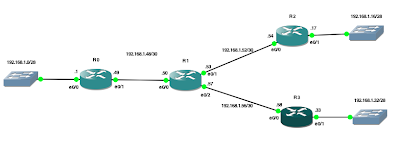
As Standard ACL's can only filter based on the source address they should be placed as near to the destination as possible. Standard access-lists can be numbered from 1-99 or 1300-1999 (expanded range). Standard access-lists can also be named. In this post I'll be using a numbered Standard ACL.


I begin by verifying connectivity before the rule is created.


R0

R0#ping r3
Type escape sequence to abort.
Sending 5, 100-byte ICMP Echos to 192.168.1.58, timeout is 2 seconds:
!!!!!
Success rate is 100 percent (5/5), round-trip min/avg/max = 4/8/16 ms


Next I create the standard access-list


R1

R1#conf t
Enter configuration commands, one per line. End with CNTL/Z.
R1(config)#ip access-list standard 1
R1(config-std-nacl)#deny host 192.168.1.49 log
R1(config-std-nacl)#permit any log
R1(config-std-nacl)#exit

I have enabled logging so I can see as each statement is hit. There is an implicit deny all statement so none is required in the access-list itself.

I place the access-list as near to the destination as possible. In this case it will be on e0/2 on R1, and it will be outgoing. Placing the list any nearer to R0 would affect traffic to R2.


R1(config)#int
R1(config)#interface ethernet 0/2
R1(config-if)#ip access-group 1 out
R1(config-if)#end


I can check the ACL with a show command.


R1#sh ip access-lists 1
Standard IP access list 1
10 deny 192.168.1.49 log (0 matches)
20 permit any log (0 matches)


I can also check which interface the rule is applied to.


R1#sh ip interface ethernet 0/2
Ethernet0/2 is up, line protocol is up
Internet address is 192.168.1.57/30
Broadcast address is 255.255.255.255
Address determined by non-volatile memory
MTU is 1500 bytes
Helper address is not set
Directed broadcast forwarding is disabled
Multicast reserved groups joined: 224.0.0.9
Outgoing access list is 1
Inbound access list is not set
Proxy ARP is enabled
Local Proxy ARP is disabled
Security level is default
Split horizon is enabled
ICMP redirects are always sent
ICMP unreachables are always sent
ICMP mask replies are never sent
IP fast switching is enabled
IP fast switching on the same interface is disabled
IP Flow switching is disabled
IP CEF switching is enabled
IP CEF Feature Fast switching turbo vector
IP multicast fast switching is enabled
IP multicast distributed fast switching is disabled
IP route-cache flags are Fast, CEF
Router Discovery is disabled
IP output packet accounting is disabled
IP access violation accounting is disabled
TCP/IP header compression is disabled
RTP/IP header compression is disabled
Policy routing is disabled
Network address translation is disabled
BGP Policy Mapping is disabled
WCCP Redirect outbound is disabled
WCCP Redirect inbound is disabled
WCCP Redirect exclude is disabled


From the output above I can see that the ACL is applied to the right interface in the right direction. Only one access-list can be applied per interface per direction.


Now I check my pings fail to reach R3 from R0

R0

R0#ping r3
Type escape sequence to abort.
Sending 5, 100-byte ICMP Echos to 192.168.1.58, timeout is 2 seconds:
U.U.U
Success rate is 0 percent (0/5)


Back on R1 I can see the deny statement has been hit.


R1

*Mar 1 00:33:33.783: %SEC-6-IPACCESSLOGNP: list 1 denied 0 192.168.1.49 -> 192.168.1.58, 1 packet


To verify that my traffic can still hit R2 I attempt to ping it from R0.


R0

R0#ping r2
Type escape sequence to abort.
Sending 5, 100-byte ICMP Echos to 192.168.1.54, timeout is 2 seconds:
!!!!!
Success rate is 100 percent (5/5), round-trip min/avg/max = 4/12/24 ms


R2

I can also check that traffic from R2 can reach R3.


R2#ping r3
Type escape sequence to abort.
Sending 5, 100-byte ICMP Echos to 192.168.1.58, timeout is 2 seconds:
!!!!!
Success rate is 100 percent (5/5), round-trip min/avg/max = 8/8/12 ms


R1

This can be seen hitting the permit statement in the access-list.


*Mar 1 00:42:00.419: %SEC-6-IPACCESSLOGNP: list 1 permitted 0 192.168.1.54 -> 192.168.1.58, 1 packet


Checking the access-list again I can see a number of hits.


R1#sh ip access-lists 1
Standard IP access list 1
10 deny 192.168.1.49 log (5 matches)
20 permit any log (5 matches)


As R3 is receiving its route updates from R1 it will still know about R0 and how to find it.

R3


R3#sh ip route
Codes: C - connected, S - static, R - RIP, M - mobile, B - BGP
D - EIGRP, EX - EIGRP external, O - OSPF, IA - OSPF inter area
N1 - OSPF NSSA external type 1, N2 - OSPF NSSA external type 2
E1 - OSPF external type 1, E2 - OSPF external type 2
i - IS-IS, su - IS-IS summary, L1 - IS-IS level-1, L2 - IS-IS level-2
ia - IS-IS inter area, * - candidate default, U - per-user static route
o - ODR, P - periodic downloaded static route

Gateway of last resort is not set

192.168.1.0/24 is variably subnetted, 6 subnets, 2 masks
C 192.168.1.32/28 is directly connected, Ethernet0/1
C 192.168.1.56/30 is directly connected, Ethernet0/0
R 192.168.1.48/30 [120/1] via 192.168.1.57, 00:00:15, Ethernet0/0
R 192.168.1.52/30 [120/1] via 192.168.1.57, 00:00:15, Ethernet0/0
R 192.168.1.0/28 [120/2] via 192.168.1.57, 00:00:15, Ethernet0/0
R 192.168.1.16/28 [120/2] via 192.168.1.57, 00:00:15, Ethernet0/0


However, R3 cannot recieving ping responses from R0 because the echo replies will be blocked by the access-list.


R3#ping r0
Type escape sequence to abort.
Sending 5, 100-byte ICMP Echos to 192.168.1.49, timeout is 2 seconds:
.....
Success rate is 0 percent (0/5)


Using a debug command on R0 I can see the pings hit the router but they cannot get back.


R0

R0#debug ip icmp
ICMP packet debugging is on
R0#
*Mar 1 00:56:11.823: ICMP: echo reply sent, src 192.168.1.49, dst 192.168.1.58
*Mar 1 00:56:11.835: ICMP: dst (192.168.1.49) administratively prohibited unreachable rcv from 192.168.1.50


I finish up by removing the ACL from the interface and the router.


R1

R1(config)#interface ethernet 0/2
R1(config-if)#no ip access-group 1 out
R1(config-if)#exit

R1(config)#no access-list 1
R1(config)#end

Saturday 27 February 2010

Configure a Router on a Stick

In this post I will configure a router to route traffic between VLANs using just one router interface, this is commonly referred to as a Router on a Stick.

Below is a diagram of the network I'll be working with in this post.


My goal is for UserA in VLAN 64 to communicate with UserB in VLAN 128. To do this my router and switch must use a fastethernet port running at 100Mb full duplex.

To begin with I will configure the ports on Switch1 to be in the correct VLANs. These commands will also create the VLANs because the don't already exist. I have named the VLANs to be the same as the networks to keep things simple.


Switch1

switch1#conf t
Enter configuration commands, one per line. End with CNTL/Z.
switch1(config)#interface range fastEthernet 0/9 - 16
switch1(config-if-range)#switchport access vlan 64
% Access VLAN does not exist. Creating vlan 64
switch1(config-if-range)#exit

switch1(config)#interface range fastEthernet 0/17 - 23
switch1(config-if-range)#switchport access vlan 128
% Access VLAN does not exist. Creating vlan 128
switch1(config-if-range)#end


I have now created the VLANs and I check this with a show command.


switch1#sh vlan brief

VLAN Name Status Ports
---- -------------------------------- --------- -------------------------------
1 default active Fa0/2, Fa0/3, Fa0/4, Fa0/5, Fa0/6, Fa0/7, Fa0/8
2 dmz active
64 VLAN0064 active Fa0/9, Fa0/10, Fa0/11, Fa0/12, Fa0/13, Fa0/14, Fa0/15, Fa0/16
128 VLAN0128 active Fa0/17, Fa0/18, Fa0/19, Fa0/20, Fa0/21, Fa0/22, Fa0/23
1002 fddi-default active
1003 token-ring-default active
1004 fddinet-default active
1005 trnet-default active


On switch2 I configure the port that will be connected to the router as a trunk port. I also configure the port to be fixed at 100Mb full duplex.


Switch2

switch2#conf t
Enter configuration commands, one per line. End with CNTL/Z.
switch2(config)#interface fastEthernet 0/2
switch2(config-if)#speed 100
switch2(config-if)#duplex full
switch2(config-if)#switchport mode trunk
switch2(config-if)#end


I check the configuration using a show command. This tells me which interfaces are trunking and for which VLANs.


switch2#sh interfaces trunk

Port Mode Encapsulation Status Native vlan
Fa0/2 on 802.1q trunking 1
Po5 desirable 802.1q trunking 1

Port Vlans allowed on trunk
Fa0/2 1-4094
Po5 1-4094

Port Vlans allowed and active in management domain
Fa0/2 1-2,64,128
Po5 1-2,64,128

Port Vlans in spanning tree forwarding state and not pruned
Fa0/2 1-2,64,128
Po5 1-2,64,128


On Router2 I create 2 sub-interfaces off the FastEthernet interface (fa0). I name these the same as the VLANs, again to keep thing simple. I also configure the sub-interfaces to support dot1q trunking.


Router2

Router2#conf t
Enter configuration commands, one per line. End with CNTL/Z.
Router2(config)#interface fastEthernet 0.64
Router2(config-subif)#encapsulation dot1Q 64
Router2(config-subif)#ip address 192.168.1.62 2 55.255.255.192
Router2(config-subif)#no shut
Router2(config-subif)#exit

Router2(config)#interface fastEthernet 0.128
Router2(config-subif)#encapsulation dot1Q 128
Router2(config-subif)#ip address 192.168.1.190 2 55.255.255.192
Router2(config-subif)#no shut
Router2(config-subif)#exit


Once the hosts are configured with valid IP addresses and subnet masks (as shown in the diagram) they are given the default gateway of the IP address that the sub-interface was configured with.


UserA
IP Address - 192.168.1.65
Subnet Mask - 255.255.255.192
Default Gateway - 192.168.1.126

UserB
IP Address - 192.168.1.129
Subnet Mask - 255.255.255.192
Default Gateway - 192.168.1.190


Now I will be able communicate between the hosts in the 2 VLANs.